The purpose of BCS100 calibration is to accurately establish the relationship between capacitance and distance between the torch head and the sheet metal, ensuring stable, efficient, and precise cutting
performance.
A new calibration must be performed after every machine startup, sheet metal replacement, or nozzle change.
First Servo Calibration (F1)
Servo calibration is used to align the motor’s motion characteristics, forming the foundation for accurate floating-head calibration and automatic height following.
Operation Steps:
1. Place the sheet metal flat on the cutting table.
2. Use the software or handheld controller to move the metal laser cutting machine head to an appropriate position above the sheet.
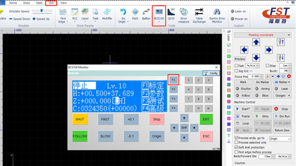
3. Open the CNC interface → click the BCS100 icon → select F1 Calibration.
4. Click 1 – Servo Calibration.
Note:
During servo calibration, the motor will make small oscillating movements.
Ensure the Z-axis is positioned near the middle of its travel to prevent overtravel during oscillation.
5. Press to start calibration. The system will complete the process automatically.
6. Once finished, return to the previous menu.
Clearing Servo Zero Drift (Optional)
If the servo zero drift value appears incorrect:
Press Clear → then press to confirm → return to the previous menu.
Second Floating-Head Calibration (F2)
Floating-head calibration establishes the correlation between sensor height and capacitance values, ensuring accurate height following during cutting.
Operation Steps:
1. Press 2 to enter the Floating-Head Calibration interface.
2. Use the downward arrow to lower the laser head until it is 1–5 mm above the sheet.
3. Make sure the sheet remains stable and free of vibration.
4. Press to begin calibration.
The automated calibration process takes approximately 10–15 seconds:
1. The floating head slowly descends until it detects the sheet surface.
2. After touching the sheet, it lifts slightly to evaluate sensor stability.
3. It then continues to move upward by the predetermined distance to assess sensor smoothness and characteristic curves.
4. Press to save. The height-capacitance curve will then be displayed.
Parameter Description:
Stability: Reflects the static performance of the capacitance signal. Poor stability may indicate plate vibration or external interference.
Smoothness: Indicates the dynamic performance of capacitance variation during calibration.
Both parameters must reach at least “Medium”, while “Good” or “Excellent” is ideal.
Effective Value: Represents the capacitance change range from 0.5 mm above the sheet to a distant position.
Higher values indicate a wider sensing range, leading to better tracking accuracy and stability.
Third Auto Adjustment (F3)
Auto adjustment fine-tunes internal parameters to ensure smoother and more responsive height following during actual cutting.
Before entering Auto Adjustment, ensure the following:
Servo calibration has been completed
The machine has been homed, and the Z-axis mechanical coordinates are correct
Floating-head calibration has been completed and is functioning properly
A sheet is positioned directly beneath the floating head for following
Operation:
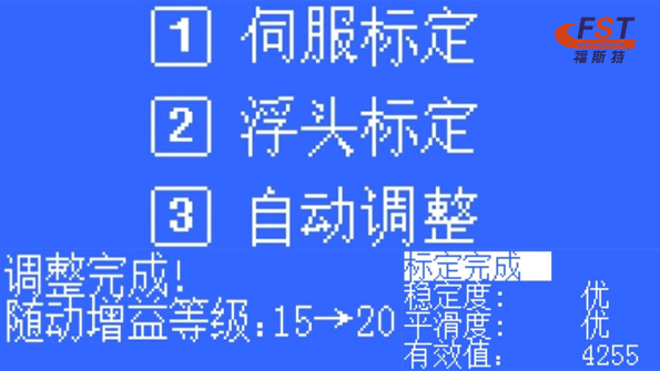
Enter the Auto Adjustment interface → the system will automatically fine-tune height-following parameters → save and exit after completion.
Calibration Complete! laser Cutter More Accurately, Smoothly, and Efficiently.
By completing all three calibration stages — Servo Calibration → Floating-Head Calibration → Auto Adjustment — the BCS100 achieves optimal height sensing and tracking performance, ensuring reliable cutting quality
every time.
Post time: Nov-14-2025

